Furnace and Preheater
 Pic. 1 Pic. 1  Pic. 2 Pic. 2
 
| - Water cooling flange on the left-side between the heater and furnace is used for pre-heated gas input and sealing
Four-channel gas inlet ( 1/8" Dia tube and tube fitting) are built-in on the left side flange One small heater is attached to the left side flange of the furnace to preheat input gas, liquid, or evaporate solid chemical, which will be then delivered to the CVD furnace: Please click the picture left for more details:
|
| Rated Voltage | Single Phase, 220V AC, 50/60 Hz, AWG 8# Power cord is included (without plug) |
| Power consumption | Max. 3600 W (20 A breaker required) |
| Heating Zone | - CVD Furnace: 440 mm
- Constant temperature zone: 100 mm
- Gas Heater: 150mm
|
| Working Temperature | - CVD Furnace:
- Max heating temperature: 1100°C ( < 2 hour )
- Continuous working temperature: 200~1000°C
- Max heating & cooling rate: 20°C/min
- Heater:
- Continuous working temperature: RT~600°C
- Max heating & cooling rate: 20°C/min
|
Temperature Control
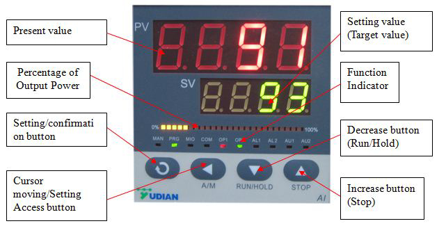
| - CVD Furnace and Heater (separate temp control):
Digital controllers with PID/self-tuning functions and 30 segments programmable Thermocouple: K type thermocouples, which feed through the right side flange and control furnace temperature. Control accuracy: +/- 1°C - RS485 Communications Port
|
Vacuum
and Gas Sealing & Flange
| The right flange of the CVD furnace
Left flange (between CVD Furnace and Heater) with four 1/8'' Swagelok fittings for 1/8'' tube:
- Two 1/8'' fitting on the flange for independently and directly delivering any gas into the CVD furnace
- One 1/8'' fitting for delivering heated gas from heater to CVD furnace
- One 1/4'' fitting for bypassing the gas (without heating) to the CVD furnace (inside the CVD furnace, the gas tube is merged with the heated gas pipe by a T fitting)
Note: How gas pipe assembled in the CVD furnace through above 1/8'' fitting:
- One 1/4'' quartz tube delivers the vapor gas from the heater(also the bypass gas by a T fitting)
- Two 1/4'' quartz tube delivery extra gas via the two separate 1/8'' fitting on the big furnace left the flange
- These three 1/4'' quartz tubes inside the CVD furnace is in parallel and vertically 1'' higher than the sample holder
- These three 1/4'' quartz tubes can be easily removed to clean or replaced once get stuck or corroded
Heater:
- Left flange: one 1/8'' gas fitting to deliver gas to the heater for pre-heating and then to the CVD furnace On the right side to the CVD furnace with necessary thermal block material to minimize the temperature gradient at the interface between the heater and CVD furnace
- Furnace Chamber Installation
- 2- 1/4" pipe adapter is installed on each flange
|
| The optional Liquid Injection device (optional) | For direct liquid CVD ( DLCVD), you may consider below devices for liquid injection: ( click Pic to order )
   |
| Net weight | 110kg |
Dimensions
 | - Standard: 62"L X 18"W X 23"H
- Maximum: 80"L X 18"W X 32"H (Lid open and right-side flange slided out)
|
| Warranty | - One year limited warranty for electrical parts. ( Consumable parts such as processing tubes, o-rings and etc are not covered by the warranty)
- You may order a replacement quartz tube here: EQ-QZTube-SF
|
Laptop, software & WiFi Control (Optional)
  | - Brand new laptop with Microsoft Windows 10 and Microsoft Office 2013 (30 days free trial)
- Labview Based Temperature Control System (EQ-MTS01) enables the user to edit temperature profiles, manage heat-treatment recipes, record, and plot data for MTI furnaces.
- A wireless remote control provides up to 300 meters of operating range.
- The above features are available upon request at an extra cost (up to $1,000). Please contact us for more information.
- Eurotherm temperature controller with software is available upon request at extra cost, which can provide +/- 0.1oC accuracy. ( see product options bar)
|
Compliance
 | - CE Certified
- NRTL(UL61010) or CSA certifications are available at extra cost.
|
Warning

Click here to learn the installation of a gas regulator | - The tube furnaces with quartz tube are designed for use under vacuum and low pressure <0.2 bars (relative to 1 atm, absolute pressure = 1.2 bar if used in air)
- Attention: A two-stage pressure regulator must be installed on the gas cylinder to limit the pressure to below 3 PSI for safe operation. Click here to learn the installation of a gas regulator.
- Vacuum pressures may only be safely used up to 1000°C
|
| Operation Demo Video & Instructions |   |


 Pic. 1
  Pic. 2


